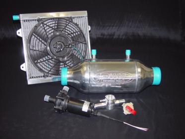
Liquid to air intercooler pump relay
What happens in case of an accident, the fuel line is ruptured, and IGN is still on? This can be both inconvenient and dangerous. Here are some applications ideally suited for the IRC:.
Intelligent Power Control Systems. Description Additional information Reviews 0 Description VaporWorx is pleased to offer a feature-rich upgrade to your relay controlled fuel pump.
Here are some applications ideally suited for the IRC: Carburetor engines and engines with a non-ECM controlled electric fuel pump. All air-to-liquid intercooler pump applications using a relay. At key-on, the IRC will energize the fuel pump relay for three seconds.
If a tachometer signal is not sensed, the IRC will de-energize the fuel pump relay. Once a tachometer signal is sensed the fuel pump relay will be energized. The temperature switch opens at a predetermined temperature at a high pressure inlet of a high pressure stage of the air compressor, thereby closing the contacts of the electrical relay which applies power to the cooling fans.
In addition, the present invention is directed to a method of installing an air compressor on a locomotive. The method includes the steps of providing an air compressor having a temperature management system and mounting the air compressor with the temperature management system at a location remote from a radiator of the locomotive. The temperature management system includes a plurality of cooling fans coupled to an intercooler of the air compressor; an electrical relay comprising a coil and contacts operated by the coil; and a temperature switch coupled with the coil of the electrical relay.
The temperature switch opens at a temperature above a predetermined temperature, thereby closing the contacts of the electrical relay which applies power to the cooling fans. The temperature switch may be closed when the temperature at the high pressure inlet falls below a second predetermined temperature, thereby opening the contacts of the electrical relay and removing power supplied to the parallel first cooling fan and second cooling fan.
These and other features and characteristics of the present invention, as well as the methods of operation and functions of the related elements of structures and the combination of parts and economies of manufacture, will become more apparent upon consideration of the following description and the appended claims with reference to the accompanying drawings, all of which form a part of this specification, wherein like reference numerals designate corresponding parts in the various figures.
For purposes of the description hereinafter, the spatial orientation terms and derivatives thereof shall relate to the embodiment as it is oriented in the drawing figures. However, it is to be understood that the invention may assume various alternative variations, except where expressly specified to the contrary.
It is also to be understood that the specific devices illustrated in the attached drawings, and described in the following specification, are simply exemplary embodiments.
Hence, specific dimensions and other physical characteristics related to the embodiments disclosed herein are not to be considered as limiting. A temperature management system as described herein has applications for use with a 2CD type air compressor, as manufactured by Wabtec Corporation, to maintain the compressor at a controlled temperature during operation.
With reference to FIGS. Air compressor 1 also includes an intercooler 9 mounted to crankcase 7. Intercooler 9 is configured to cool the air between low pressure stage 3 and high pressure stage 5. Intercooler 9 is constructed from a plurality of copper or aluminum finned tubes A relief valve 13 is mounted on intercooler 9 for the purpose of limiting pressure build-up in intercooler 9. Compressor 1 may be driven directly off the locomotive's diesel engine through appropriate couplings and a drive shaft or it may be belt driven by an electric motor not shown operatively coupled to a drive pulley The temperature management system is intended to maintain high pressure stage inlet air at a proper operating temperature.
This temperature is desirably cool enough to avoid component overheating and warn enough to avoid condensation of water within the intercooler. Both conditions can lead to premature wear and failure. The temperature management system includes a temperature switch 17 positioned at a high pressure stage inlet 19 of high pressure stage 5.
Additional control circuitry, as will be discussed in greater detail hereinafter, is positioned within an electrical enclosure 21 and a pair of cooling fans 23 , electrically coupled in parallel, coupled to intercooler 9.
With reference to FIG. Temperature management system includes a load circuit 27 and a switching circuit Load circuit 27 includes the pair of cooling fans 23 electrically coupled in parallel, and contacts 31 of an electrical relay 33 located in a series between the pair of cooling fans 23 and an electrical power supply.
Switching circuit 29 includes temperature switch 17 and a coil 35 of electrical relay 33 provided in a series with temperature switch The electrical power supply supplies 24 VDC. A 15A fused line 37 is provided to power load circuit 27 , and a 1A fused line 39 is provided to power switching circuit The operation of temperature management system 25 is as follows. This position holds the normally closed electrical relay 33 in the energized open position shown in phantom in FIG.
In this state, cooling fans 23 are off. When coil 35 de-energizes, contacts 31 of the electrical relay 33 close, thereby applying power to the pair of cooling fans 23 causing them to start.
At that air temperature, temperature switch 17 closes, thereby energizing coil 35 of electrical relay 33 and opening contacts This turns off cooling fans Failure of temperature switch 17 causes contacts 31 of electrical relay 33 to close which applies power to the parallel cooling fans Accordingly, temperature management system 25 is failsafe.
If temperature switch 17 fails or is not powered, fans 23 will turn on as long as power is supplied to load circuit 27 via the normally closed electrical relay Temperature management system 25 provides air compressor 1 with various advantages over existing compressors. Cooling fans 23 provide air compressor 1 with an integral source of cooling air that previously was completely supplied by external means via a radiator or other cooling fan on board the locomotive.
Accordingly, air compressor 1 with temperature management system 25 does not need to be mounted directly in the proximity of the radiator or other cooling fans of the locomotive. It may be mounted at any suitable location on the locomotive. For example, compressor 1 may be mounted in a rear compartment of the locomotive with the compressor axis mounted in any orientation.
In other words, the axis of the compressor shaft may be placed perpendicular to the direction of travel of the locomotive. Compressor 1 may also be placed on an elevated platform above the locomotive deck or to one side of the locomotive longitudinal axis to allow room for other auxiliary equipment.
Accordingly, in many ambient conditions, it is possible that no external cooling fans will be required for the purpose of providing cooling air to air compressor 1. In addition, due to the operating nature of a multiple stage compressor with inter-stage cooling, the internal temperatures of the compressor must be held high enough to avoid the internal condensation of water.
However, too little cooling will cause the compressor to be less efficient and in extreme cases, will lead to compressor failure. In order to maintain a proper operating temperature, prior art 2CD type compressors are typically located directly beneath the locomotive radiator for overheating protection and minimum compressor operating temperatures are maintained by never turning the compressor off when in use.
By providing air compressor 1 with pair of cooling fans 23 that can be controlled to provide the necessary amount of cooling or to provide no cooling, air compressor 1 with temperature management system 25 can quickly achieve minimum operating temperatures and at the same time be protected from exceeding maximum operating temperatures. Furthermore, as a direct result of the requirement to always spin the compressor when in operation, methods to drive the compressor are limited.
It has become standard design procedure to mount the compressor directly inline with the locomotive crankshaft via a coupling. In this configuration, the prior art compressor was always turning when the locomotive engine was running. However, this forces the locomotive builder to place the compressor inline with the engine and turn the compressor at the engine speed of the locomotive.
Another option was to mount the compressor perpendicular to the locomotive driveshaft and gear down the compressor speed using a belt or gear box type drive. This provides the locomotive designer with great flexibility in locating air compressor 1. Air compressor 1 with temperature management system 25 does not need to be positioned inline or perpendicular to the locomotive driveshaft and in most cases does not require direct cooling air from an external source.
Accordingly, air compressor 1 with temperature management system 25 can be positioned in any suitable location on the locomotive. However, driving air compressor 1 with an electric motor also allows the compressed air delivery to meet the compressed air demand by varying the speed of the electric motor independently of the locomotive engine speed. Since air delivery is proportional to compressor rotational speed, the air delivery can meet the exact air demand without wasting unnecessary power.
Although the invention has been described in detail by illustrative embodiments, it is to be understood that such detail is solely for that purpose and that the invention is not limited to the disclosed embodiments, but, on the contrary, is intended to cover modifications and equivalent arrangements.
For example, it is to be understood that the present invention contemplates that, to the extent possible, one or more features of any embodiment can be combined with one or more features of any other embodiment.