US3894812A - Liquid ring vacuum pump-compressor - Google Patents
5 stars based on
56 reviews
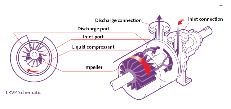
Freeh Assistant Examiner-Richard E. ABSTRACT A single stage axial flow liquid ring pump having separate rotor blade zones for suction and for di permitting use of contoured blade an to reduce fluidic shock, reduce noise performance by reduction of sli losses. The liquid ring principle is a well established art. Typically, a liquid ring pump consists of a multi-bladed rotor mounted on a shaft and arranged so as to rotate freely within an eccentric or elliptical casing.
Water introduced in the casing is acted upon by the blades of the rotor. As the ring surges outward and inward in alteration it creates a piston action in the buckets formed by the rotor blades.
Port openings, either centrally located or on the sides of the rotor. The efficiency of a liquid ring vacuum pump or compressor is determined by the relationship of actual energy required to pump a gas as related to the theoretical work energy required. The difference between actual and theoretical represents energy losses. In liquid ring pumps these losses consist mainly of [at friction losses caused by liquid ring velocity in the pump casing. Of these sources of loss of efficiency those losses due to casing friction are determined by the properties of the liquid comprising the ring.
This invention does address itself to the other two causes of efficiency losses; those of internal gas slippage, and hydraulic losses. In the design of liquid ring pumps there are two common arrangements for directing the gas into and out of the pumping chamber. The inlet and discharge ports are arranged either on flat plates on the side of an open bladed rotor.
In both instances the port memher is stationary and the liquid ring vacuum pump pdf reader is in rotation and in very close contact with the port opening. In the circular or single lobe design there is one pumping cycle per revolution of the rotor.
On elliptical or twolobe designs there are two pumping cycles per revolution and hence two inlet and discharge ports. In the known art the inlet and discharge ports are located adjacently on the same surface. In the case of flat sided pumps the inlet and discharge ports are located on a common flat plate with the discharge port displaced from the inlet port in the direction of rotation.
In designs employing a central port cylinder or cone the inlet and discharge ports are likewise located on the same surface, this surface being formed by the periphery of the cone or port cylinder.
The discharge port is likewise displaced from the inlet port in the direction of rotation. The arrangements as described above make it imperative that the clearances between the rotating rotor portion and the stationary ported portion be as tight as possible so as to minimize slippage losses liquid ring vacuum pump pdf reader inlet and discharge ports. In common practice the displacement of the inlet and discharge ports is approximately twenty degrees of are or one-third radian.
This arrangement dictates that the points of greatest and least pressure are displaced from each other by only a relatively small gap. In order to minimize slippage losses it is necessary to set the clearances as close as possible and also provide liquid ring vacuum pump pdf reader liquid injection between parts in rotation. The liquid used to seal the clearances makes its way to the liquid ring and then to discharge. As wear progresses in the pump its water requirements are increased to meet the increased sealing requirements.
It is obvious that slippage losses are increased when the pressure differential between inlet and discharge is increased. For this reason single stage vacuum pumps are normally good for operation up to 27 inches Hg vacuum. The improved design described in the invention reduces slippage losses and permits operation up to twenty-nine inches Hg vacuum in single stage a three fold improvement over existing single stage pump designs.
Existing pump designs require complex passages to direct the flow of gas and liquid into the pump and to discharge. On flat sided pumps the chamber comprising the inlet is compartmcnted so that the incoming gas is directed liquid ring vacuum pump pdf reader one or more inlet ports. These passageways are located in the heads which are located outboard from the port plate. Centrally located port cylinders and cones also require compartmentation ofthe internal porting members and also the pump heads.
These complicated passageways constrict the flow of fluids and cause friction losses. They furthermore complicate the casting. Because ofthe complexity of existing designs the port openings are normally of intricate design and are formed in the casting process. Because of the necessity of separating suction and discharge passages, the use of sleeves on parts in close or sliding contact is not used.
Parts subject to wear are either replaced, remachined. This invention simplifies pump construction and permits the economical use of sleeves of any suitable material. Liquid ring pumps of current designs utilize rotor blades which. For example, in a centrally ported design the rotor blades spin around a centrally located port cylinder. As the rotor blade passes over liquid ring vacuum pump pdf reader suction port the receding liquid ring pulls air or gas radially outward into the chamber formed by the blades and rotor shrouds.
As the blades pass over the discharge port the gas or air is displaced radially inwardly into the discharge port. To perform these dual functions the blade at the point of contact with the port must be approximately from the direction of rotation. This necessary arrangement creates hydraulic or fluidic shock because the blade shears the gas and liquid stream. The result of this fluidic shock is friction loss liquid ring vacuum pump pdf reader high noise level.
In the improved pump described in this invention the suction and discharge portions of the rotor blades are displaced from each other, permitting the use of angular contact of blade to fluid stream, thus reducing fluidic shock and substantially reducing the noise caused by the fluid stream shear.
It is a primary object of the invention to provide a means whereby the suction port is removed from close proximity to the discharge port so as to reduce slippage losses caused by liquid ring vacuum pump pdf reader bypassing from the discharge port to the lower pressure suction ports.
This feature greatly improves pump efficiency and permits operation with water seal in single stage out to twenty nine inches Hg vacuum. This improvement is also significant when the pump is used as a compressor. Disassociation of the inlet and discharge port is achieved by placing the suction port or ports on a flat plate located beside the rotor.
The rotor blades are either open or shrouded at the point of contact with the port plate. The discharge port, or ports, are placed on a central port cylinder or cone. The rotor blades communicate with the discharge port by means of openings on the rotor inner bore, and air or gas and accompanying liquid is discharged radially into the central porting member, and thence axially to pump discharge.
This separation of the functions of the suction and discharge porting reduces slippage losses to a minimum. A further object of the invention is to provide for efficient pump operation in the full operating range with relatively loose clearances. Because the suction and discharge ports are not in close proximity. Thus, the pump may be expected to perform satisfactorily with worn parts whereas a conventional pump would suffer serious loss of capacity and ability to attain high vacuum.
A further object of the invention is to simplify the conduits and passage through which the fluids must travel from inlet to final discharge. By disassociating suction and discharge functions the inlet ports are simply connected to a common suction chamber.
The discharge ports are likewise connected to a common chamber. The flow of fluids is unimpeded. This benefit is of particular importance on double lobe or multiple lobe pump designs where congestion of passages is a serious handicap with existing pump designs. It is an object of the invention to provide axial flow through the pump. An important object of the invention is to permit the use of a sleeve on the discharge port cylinder. While sleeves perhaps could be adapted to other pumps utilizing the central port cylinder design, such designs currently have both suction and discharge ports located in the port cylinder, and bonding the sleeve to the port cylinder so as not to have any leakage or communication between inlet and discharge ports would be a difficult and costly process.
Liquid ring vacuum pump pdf reader of sleeves to the pump design covered by this invention is easy and inexpensive. A corollary benefit and object of this invention is the use of special seal materials such as fluorinated hydrocarbons of the Teflon family.
Such seal materials are self lubricating and this lubricity permits operating the mating port cylinder and rotor with sliding contact, further reducing slippage losses.
Other sleeve materials are also a part of the scope of this invention as benefits can be gained by the use of rubber and urethane materials for abrasion resistance, titanium and copper nickel alloys for chloride resistance, stainless steel, bronzes and ceramics for special applications.
It is obvious that the cost of sleeve fitted parts, made possible by this invention, would be far less than the cost of fabricating the entire part from a special material. There are further benefits to be gained in relation to liquid ring vacuum pump pdf reader replacement and servicing the pumps. An additional feature of the invention is the compartmentalizing of the mechanical seal in such way that the seal cooling fluid removes heat from the seal faces and then is introduced into the pump.
The mechanical liquid ring vacuum pump pdf reader is thus always kept under positive pressure, even on vacuum service. When the vacuum pump or compressor is handling dirty gases or gases of a corrosive nature these impurities or corrosives cannot enter the mechanical seal area, thus ensuring satisfactory seal life even under extreme operating conditions. Frequently vacuum pumps on liquid ring vacuum pump pdf reader vacuum service, such as vacuum filtration, are subjected to slugs of liquids containing sand, grit or impurities, and these impurities could not affect the mechanical seal.
A primary feature of the invention is the unique means whereby the rotor blade area in contact with the suction port is not associated with the discharge port. Likewise, the rotor blade area in contact with the discharge port is not in contact with the suction port. By utilizing separate blade areas for different functions, it is possible to design the blade to provide optimum performance.
To accomplish this the suction blade area is liquid ring vacuum pump pdf reader toward the direction of flow so that instead of shearing the fluid flow at the blade can slice the fluid at an angle optimized for the blade and fluid relative velocities.
The air foil in the trailing edge of the blade at the suction port creates a vacuum which assists in sucking air or gas into the buckets formed by the receding liquid ring. Conversely, by having the leading edge of the blade at the discharge port angle back away from the direction of rotation the discharge of air and water is smoothed resulting in reduction in pulsation and higher discharge compression.
The use of contour blade areas as liquid ring vacuum pump pdf reader in the invention at the inlet and discharge portions reduces substantially the noise caused by fluidic shock as well as improves over all pump efficiency, both as vacuum pump and compressor.
Another feature of the invention is the use of guide vanes in the suction and discharge ports so as to direct the fluid flow to obtain the optimum contact angle between the rotor blade and fluid stream. The addition of guide vanes results in improved efficiency and substantially reduced noise.
The guide vanes offer an additional benefit when the pump is required to handle large quantities of liquid, or liquid slugs. The vanes absorb hydraulic shock by breaking up the liquid stream before it comes into contact with the rotor blades.
I is a longitudinal sectional view of the liquid ring pump according to the invention. I illustrating the pump of FIG. I provided with a single lobe. I provided liquid ring vacuum pump pdf reader a double lobe. The shaft I2 is provided with sleeve I6 at the area of the mechanical seal assembly The rotor 11 rotates freely within casing I8 which forms one or more lobes I9 depending on the design which are eccentric to the rotor centerline.
The rotor rotates around a port cylinder on which sleeve 21 is secured. The port cylinder 20 is secured to the casing 18 and is held stationary. The casing 18 is bolted to the suction member, or head 22 which is shown bolted to motor The head is provided with gas inlet connection 24, seal water inlet connection 25, and suction gas manifold 26 which connects to suction port The suction port liquid ring vacuum pump pdf reader is cast or machined through the wall 28 of suction member or head