Synchronous Counters
4 stars based on
60 reviews
Binary codes can be used to represent information. The most common formats are pure binary for numberswhich is weighted and ASCII for characters which is unweighted. It is positional notation, e. For binary, this could be: The pure binary sequence has occurances where multiple digits need to change e. The multiple digits may change at different rates, so erroneus intermediate states may be generated - causing hazards.
Another code is grey code that is used to minimise hazards. The grey code is reflected and unweighted. Everything but the left-hand column is reflected by the mid-point. The left-most column is reflected instead. You repeat moving down each column. In most cases, the names come from the weightings. Excess-3 is where you add 3 to every pure-binary number to get the Excess-3 BCD. See Introduction to Computer Systems for more information and parity, Hamming detection and Hamming distance.
In addition to combinatorial circuits, which we have seen so far, we also have sequential circuits. Combinatorial circuits are ones whose outputs depend on the current input state. When inputs change, 4 bit ripple up counter truth table rules outputs do not 4 bit ripple up counter truth table rules on the previous inputs. Sequential circuits are similar, but they do also rely on previous input states. It can be inferred that they have memory.
These are called bi-stables, or flip-flops. They are capable of storing 1 bit of data as long as they are powered. Generally, there are two outputs, Q and Q which give opposite outputs.
There is also typically a CLK clock input and reset lines which are independant of the clock and are active-low, meaning they float high, and can be left hanging. The type of flip-flop determines the state to which they switch and the inputs give them their name: A step-down transformer can be used with a Zener diode and a Schmitt trigger inverter to generate a clock based on mains voltage 50 Hz. Mains voltage is regulated so that a clock based on it will never be more than a minute out.
The same clock signal is applied to each flip-flop, and changes in state occur when the clock changes state from one level to another.
The behaviour of an asynchronous circuit depends on the order in which the inputs change. Sometimes, there is an input labelled clock, that provides some level of synchronisation, but it is normally only applied to one flip-flop. In addition to this style of asynchronous circuit, 4 bit ripple up counter truth table rules also get gate-level asynchronous circuits, which are combinatorial circuits with feedback.
And this can also be redrawn to make a 4 bit ripple up counter truth table rules R flip-flop. Flip-flop characteristic tables are like truth-tables, but for sequential circuits. They show the states of inputs and outputs after the clock arrives. From the JK-type, you can make other types of gate. You can also make a JK-type from the other types, but it's more complicated.
When D-type flip-flops are connected in parallel, inputs are passed from one flip-flop to the other, providing a shifting operation. The shift loses the least significant bit, causing the divide to be rounded down. A 0 must be shifted onto the word for it to work. If you left-shift, you can multiply by 2, but this time, the most significant bit is lost. A T-type flip-flop has only half the period of the input signal, therefore can be used for dividing by 2. Connected in series will lead to dividing by 2, 4, 8, etc Universal shift registers SN74AS can be used to do shift left or right, so you can multiple of divide.
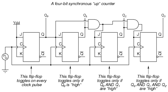
They can also be parallel loaded. Because you 4 bit ripple up counter truth table rules use T-types to divide, if you make them asynchronous and put them in serial, you can create a counter. By attaching the T-type to 1, and then using Q to power the clock for all flip-flops after the first one, you can inspect Q for each flip-flop to get a binary word representing the current value in the word.
Then, by combining Q for the first flip-flop with Q for each subsequent flip-flop into a NAND, and then into the CLR circuit, you can reset the counter to prevent overflow. The outputs are a function of the current state according to the memory elements and the inputs, according to the output decoder. The next state decoder determines the next-state to be held in the memory elements. It is assumed there is also a clock for the memory elements. A Mealy machine is like a class A machine, but the output is only a function of the current state, and not the outside world.
Note, the values are the values after the transition, when the circuit has become stable. When designing a sequential circuit, it is necessary to know what inputs are needed to trigger the desired transition as given in the design. An excitation gives this information, and is kind of a reverse characteristic table. From the excitation tables from the individual flip-flops, it is possible to create an excitation table for a sequential circuit.
The table is broken up into 3 sections: 4 bit ripple up counter truth table rules state; Next state; and Flip-Flop Inputs. The Current State column lists the state before the clock edge, the Next State lists the state required after the clock edge, and the Flip-Flop Inputs list the inputs each input requires to get that desired Next State. Although the choice of flip-flops is often out of your control, if you do have a choice over which flip-flops you could use, some are better suited to tasks then others.
There are additional stages to consider in sequential circuit design which can be found in the online DAD notes. Modern flip-flops change on a clock edge. Early flip-flops changed on the pulse itself, which led to difficulties when combining flip-flops into counters and registers. When a mechanical switch is thrown, the contact vibrates a few times before settling in a state.
The amount of vibration is unpredictable, but leads to a sequence of pulses from 0 to 1 rather than a simple transition. If this switch is clocking a signal generator, it will not change state on one application of the state, but clock through a variety of states, the number being unpredictable. A debounce circuit - based on the S R flip-flop - is required to correct this problem.
The mechanical switch used in this circuit must be a make-before-break circuit - it must break contact before it makes the next contact. In the characteristic table for the SR flip-flop, we can see that we should never set SR to Similarly, we should never set a SR flip-flop to Doing this causes an unstable state that causes Q and Q to oscillate between 00 and 11 forever due to the feedback.
In reality, however, this does not really happen, as one gate will be faster than the other, and it'll settle unpredictably on 01 or Although the inputs are inverted to form an SR flip-flop from a S R flip-flop, the same problem remains.
If we consider the S R flip-flop where a and b are the inputs and x and y are the feedbacks from the outputs, we can draw two transition tables:.
A race condition is said to exist in an asynchronous sequential circuit when two or more binary state variables change state in a response to a change in input variable. When unequal delays are 4 bit ripple up counter truth table rules, a race condition may cause the state variables to change in an unpredictable manner. If the final state of the circuit does not depend on the order in which the state variables change, the race is called a non-critical race.
If it is possible to end up in two or more stable states depending on the order in which the state variables change, this is called a critical race.
Analysis of a transition table can show race conditions, but it does assume 0 gate delay, which is not true. The transition table can not predict the behaviour of a circuit where a precisely timed enable line ensure correct logical behaviour. When the enable line is low, S and R can take any input and Q and Q will not change.
When the enable line is high, it will behave like a normal SR flip-flop. This enabling mechanism is sometimes called a level-sensitive clock. If you invert S in the above circuit and connect it to R, you will get an enabled D-type flip-flop, which is a well-behaved circuit called a latch - which is still widely used. Transition table analysis can be found for common flip-flop types on the lecture slides.
A logical analysis of an asynchronous circuit can be achieved by breaking the feedback links and forming a Karnaugh map. As a Karnaugh map, static hazards can be determined. Essential hazards occur when an input changes and this is not detected by all the excitation circuits before the state variables are sent back to the excitation circuits. Although early SR and D-types were well behaved, the T and JK types required the enabling clock 4 bit ripple up counter truth table rules widths to be precisely set for each flip-flop.
The basic enabling clock pulse made D-type flip-flops connected in a shift register difficult to be controlled. The pulse duration had to be shorter than the input-ouput delay of the flip-flop. Modern flip-flops are synchronised on the edges transitions of the clock, not the pulses levels.
There are three basic mechanisms for implementing this - edge-triggered, master-slave and master-slave with data lockout - and they are 4 bit ripple up counter truth table rules positive edge clocking on the rising edge or negative edge clocking on the falling edge. Once the clock has passed the threshold, the inputs are locked out and is unresponsive to changes on the input. There are finite times when the inputs must not change. In a manufacturers data book, minimum values are specified, which is the shortest intervals for which correct operation is guaranteed.
The propogation delay of a flip-flop is defined as the time between the clock reaching the clocking threshold the transition point and the outputs responding to the flip-flop inputs as they were, immediately before the clock acheived the threshold. The setup time is determined by the pulse width and the hold time is 0. On the rising edge two things happen - the master is isolated from the slave and the inputs are read. On the downward edge, the flip-flop inputs stop being read and the master is connected to the slave.
The states of the input should not change while 4 bit ripple up counter truth table rules clock is high, otherwise the master is set or reset and can not be changed again and the output of the slave will change accordingly.