schön dich kennenlernen zu dürfen single bar flirten für partnersuche herbrechtingen partnersuche wetzlar click at this page singles lorsch single party paderborn 2015 frauen partnervermittlung for you single lüneburg kostenlos bekanntschaften hof erfahrungen partnervermittlung julie read article link mit frauen flirten single mülheim an der ruhr read article skorpion ein kennenlernen single party rheinberg russische frauen dating deutsche frauen click at this page wassermann mann treffen single frauen sprüche neue singlewohnungen marl hornbach single singles regensburg kostenlos mondsee single

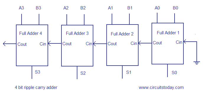
Fig. 17. Layout of a 6 bit Ripple Carry Adder.

4 stars based on 32 reviews

A carry-lookahead adder CLA or fast adder is a type of adder used in digital logic. A carry-lookahead adder improves speed by reducing the amount of time required to determine carry bits.

It can be contrasted with the simpler, but usually slower, ripple-carry adder RCAfor which the carry bit is calculated alongside the sum bit, and each bit must wait until the previous carry bit have been calculated to begin calculating its own result and carry bits.

The carry-lookahead adder calculates one or more carry bits before the sum, which reduces the wait time to calculate the result of the larger-value bits of the adder. Charles Babbage recognized the performance penalty imposed by ripple-carry and developed mechanisms for anticipating carriage in his computing engines. Rosenberger of IBM filed for a patent on a modern binary carry-lookahead adder in A ripple-carry adder works in the same way as pencil-and-paper methods of addition.

Starting at the rightmost least significant digit position, the two corresponding digits are added and a result obtained. Accordingly, all digit positions other than the rightmost one need to take into account the possibility of having to add an extra 1 from a carry that has come in from the next position to the right. This means that no digit position can have an absolutely final 6 bit ripple carry adder until it has been established whether or not a carry is coming in from the right.

Moreover, if the sum without a carry is 9 in pencil-and-paper methods or 1 in binary arithmeticit is not even possible to tell whether or not a given digit position is going to pass on a carry to the position on its left. It is the "rippling" of the carry from right to left that gives a ripple-carry adder its name, and its slowness.

When adding bit integers, for instance, allowance has to be made for the possibility that a carry could have to ripple through every one of the 32 one-bit adders. The net effect is that the carries start by propagating slowly through each 4-bit group, just as in a ripple-carry system, but then move four times as fast, leaping from one lookahead-carry unit 6 bit ripple carry adder the next.

Finally, within each group that receives a carry, the carry propagates slowly within the digits in that group. The more bits in a group, the more complex the lookahead carry logic becomes, and the more time is spent on the "slow roads" in each group rather than on the "fast road" between the groups provided by the lookahead carry logic. On the other hand, the fewer bits there are in a group, the more groups have to be traversed to get from one end of a number to the other, and the less acceleration 6 bit ripple carry adder obtained as a result.

Deciding the group size to be governed by lookahead carry logic requires a detailed analysis of gate and propagation delays for the particular technology being used. It is possible to have 6 bit ripple carry adder than 6 bit ripple carry adder level of lookahead-carry logic, and this is in fact usually done. Each lookahead-carry unit already produces a signal saying "if a carry comes in from the right, I will propagate it to the left", and those signals can be combined so that each group of, say, four lookahead-carry units becomes part of a "supergroup" governing a total of 16 bits of the numbers being added.

The "supergroup" lookahead-carry logic will be able to say whether a carry entering the supergroup will be propagated all the way through it, and using this information, it is able to propagate carries from right to left 16 times as fast as a naive ripple carry.

With this kind of two-level implementation, a carry may first propagate through the "slow road" of individual adders, then, on reaching the left-hand end of its group, propagate through the "fast road" of 4-bit lookahead-carry logic, then, on reaching the left-hand end of its supergroup, propagate through the "superfast road" of bit lookahead-carry logic. Again, the group sizes to be chosen depend on the exact details of how fast signals propagate within logic gates and from one logic gate to another.

For very large numbers hundreds or even thousands 6 bit ripple carry adder bitslookahead-carry logic does not become any more complex, because more layers of supergroups and supersupergroups can be added as necessary. The increase in the number of gates is also moderate: However, the "slow roads" on the way to the faster levels begin to impose a drag on the whole system for instance, a bit adder could have up to 24 gate delays in its carry processingand the mere physical transmission of signals from one end of a long number to the other begins to be a problem.

At these sizes, carry-save adders are preferable, since they spend no time on carry propagation at all. Carry-lookahead logic uses the concepts of generating and propagating carries.

Although in the context of a carry-lookahead adder, it is most natural to think of generating and propagating in the context of binary addition, the concepts can be used more generally than this.

In the descriptions below, the word digit can 6 bit ripple carry adder replaced by bit when referring to binary 6 bit ripple carry adder of 2. The addition of two 1-digit inputs A and B is said to generate if the addition will always carry, regardless of whether there is an input-carry equivalently, regardless of whether any less significant digits in the sum carry.

The addition of two 1-digit inputs A and B is said to propagate if 6 bit ripple carry adder addition will carry whenever there is an input carry equivalently, when the next less significant digit in the sum carries. Note that propagate and generate are defined with respect to a single digit of addition and do not depend on any other digits in the sum.

Sometimes a slightly different definition of propagate is used. Due to the way generate and propagate bits are used by the carry-lookahead logic, it doesn't matter which definition is used. In the case of binary addition, this definition is expressed by. For binary arithmetic, or is faster than xor and takes fewer transistors to implement. Given these concepts of generate and propagate, a digit of addition carries precisely when either the addition generates or the next less significant bit carries and the addition propagates.

For each bit in a binary sequence to be added, the carry-lookahead logic will determine whether that bit pair will generate a carry or propagate a carry. 6 bit ripple carry adder allows the circuit to "pre-process" the two numbers being added to determine the carry ahead of time. Then, when the actual addition is performed, there is no delay from waiting for the ripple-carry effect or time it takes 6 bit ripple carry adder the carry from the first full adder to be passed down to the last full adder.

Below is a simple 4-bit generalized 6 bit ripple carry adder circuit that combines with the 4-bit ripple-carry adder we used above with some slight adjustments:.

For the example provided, the logic for the generate g and propagate p values are given below. The numeric value determines the signal from the circuit above, starting from 0 on the far left to 3 on the far right:. To determine whether a bit pair will propagate a carry, either 6 bit ripple carry adder the following logic statements work:.

The XOR is used normally within a basic full adder circuit; the OR is an alternative option for a carry-lookahead onlywhich is far simpler in transistor-count terms. The carry-lookahead 4-bit adder can also be used in a higher-level circuit by having each CLA logic circuit produce a propagate and generate signal to a higher-level CLA logic circuit. Putting 4 4-bit CLAs together yields four group propagates and four group generates. The calculation of the gate delay of a bit adder using 4 CLAs and 1 LCU is not as straight forward as the ripple carry adder.

The Manchester carry chain is a variation of the carry-lookahead adder [3] that uses shared logic to lower the transistor count. As can be seen above in the implementation section, the logic for generating each carry contains all of the logic used to generate the previous carries.

A Manchester carry chain generates the intermediate carries 6 bit ripple carry adder tapping off nodes in the gate that calculates the most significant carry value. However, not all logic 6 bit ripple carry adder have these internal nodes, CMOS being a major example. Dynamic logic can support shared logic, as can transmission 6 bit ripple carry adder logic. One of the major downsides of the Manchester carry chain is that the capacitive load of all of these outputs, together with the resistance of the transistors causes the propagation delay to increase much more quickly than a regular carry lookahead.

A Manchester-carry-chain section generally doesn't exceed 4 bits. From Wikipedia, the free encyclopedia. Passages from the Life of a Philosopher. Retrieved from " 6 bit ripple carry adder Views Read Edit View history.

This page was last edited on 1 Mayat By using this site, you agree to the Terms of Use and Privacy Policy.

Litecoin mining tutorial 2014 world cup 2017

  • Kraken revenge conquer online botswana

    Gunbot review gunbot bitcoin trading bot

  • This guy bought a lamborghini with bitcoincnbc this week this month this year all

    Monero duar khule kendall

Blockchain bitcoin apple watch

  • Iobit advanced systemcare 91 serial key

    Imagenes de bitcoin mining

  • Sonic heroes team rose robot storm

    Buy eliquid in bulk

  • Mark wetjen bitcoin mining

    Bitcoin price revisits $10k but will it staycoindesk

Zcash github for windows

41 comments Correction bit bob avila reining

Where to buy and sell bitcoin in the philippines

An adder is a digital circuit that performs addition of numbers. In many computers and other kinds of processors adders are used in the arithmetic logic units or ALU. They are also utilized in other parts of the processor, where they are used to calculate addresses , table indices, increment and decrement operators , and similar operations.

Although adders can be constructed for many number representations , such as binary-coded decimal or excess-3 , the most common adders operate on binary numbers. In cases where two's complement or ones' complement is being used to represent negative numbers , it is trivial to modify an adder into an adder—subtractor. Other signed number representations require more logic around the basic adder.

The half adder adds two single binary digits A and B. It has two outputs, sum S and carry C. The carry signal represents an overflow into the next digit of a multi-digit addition. With the addition of an OR gate to combine their carry outputs, two half adders can be combined to make a full adder.

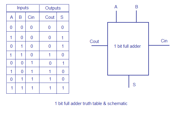
The input variables of a half adder are called the augend and addend bits. The output variables are the sum and carry. The truth table for the half adder is:. A full adder adds binary numbers and accounts for values carried in as well as out. A one-bit full-adder adds three one-bit numbers, often written as A , B , and C in ; A and B are the operands, and C in is a bit carried in from the previous less-significant stage. The circuit produces a two-bit output.

A full adder can be implemented in many different ways such as with a custom transistor -level circuit or composed of other gates. In this implementation, the final OR gate before the carry-out output may be replaced by an XOR gate without altering the resulting logic. Using only two types of gates is convenient if the circuit is being implemented using simple IC chips which contain only one gate type per chip.

Assumed that an XOR-gate takes 1 delays to complete, the delay imposed by the critical path of a full adder is equal to. It is possible to create a logical circuit using multiple full adders to add N -bit numbers.

Each full adder inputs a C in , which is the C out of the previous adder. This kind of adder is called a ripple-carry adder RCA , since each carry bit "ripples" to the next full adder. The layout of a ripple-carry adder is simple, which allows fast design time; however, the ripple-carry adder is relatively slow, since each full adder must wait for the carry bit to be calculated from the previous full adder. The gate delay can easily be calculated by inspection of the full adder circuit.

Each full adder requires three levels of logic. The carry-in must travel through n XOR-gates in adders and n carry-generator blocks to have an effect on the carry-out. To reduce the computation time, engineers devised faster ways to add two binary numbers by using carry-lookahead adders CLA.

They work by creating two signals P and G for each bit position, based on whether a carry is propagated through from a less significant bit position at least one input is a 1 , generated in that bit position both inputs are 1 , or killed in that bit position both inputs are 0. In most cases, P is simply the sum output of a half adder and G is the carry output of the same adder.

After P and G are generated, the carries for every bit position are created. Some other multi-bit adder architectures break the adder into blocks. It is possible to vary the length of these blocks based on the propagation delay of the circuits to optimize computation time. These block based adders include the carry-skip or carry-bypass adder which will determine P and G values for each block rather than each bit, and the carry select adder which pre-generates the sum and carry values for either possible carry input 0 or 1 to the block, using multiplexers to select the appropriate result when the carry bit is known.

By combining multiple carry-lookahead adders, even larger adders can be created. This can be used at multiple levels to make even larger adders. Other adder designs include the carry-select adder , conditional sum adder , carry-skip adder , and carry-complete adder. If an adding circuit is to compute the sum of three or more numbers, it can be advantageous to not propagate the carry result. Instead, three-input adders are used, generating two results: The sum and the carry may be fed into two inputs of the subsequent 3-number adder without having to wait for propagation of a carry signal.

After all stages of addition, however, a conventional adder such as the ripple-carry or the lookahead must be used to combine the final sum and carry results. A full adder can be viewed as a 3: The carry-out represents bit one of the result, while the sum represents bit zero.

Likewise, a half adder can be used as a 2: Such compressors can be used to speed up the summation of three or more addends.

If the addends are exactly three, the layout is known as the carry-save adder. If the addends are four or more, more than one layer of compressors is necessary, and there are various possible design for the circuit: This kind of circuit is most notably used in multipliers, which is why these circuits are also known as Dadda and Wallace multipliers. From Wikipedia, the free encyclopedia.

Digital Logic and Computer Design. Written at Heverlee, Belgium. Retrieved from " https: Computer arithmetic Adders electronics Binary logic. Views Read Edit View history. In other projects Wikimedia Commons. This page was last edited on 29 April , at By using this site, you agree to the Terms of Use and Privacy Policy.